Greensteam
Sustainable steam power for the 21st century
External combustion steam power was the power that created the industrial revolution. For 150 years the greatest engineering minds contributed to its constant improvement. It was largely the easy availability of a high energy liquid fuel that led to the rise of the internal combustion engine, adapted primarily for transportation applications.
External combustion steam power has distinct advantages, especially for stationary systems. The key advantage for the research and design process is that, contrary to the internal combustion paradigm, the production of energised fluid is entirely separable from mechanical and electric power generation. Because of this separability, development of novel compact, simple and efficient engine designs can occur independent of research into combustion of different fuels.
Steam power is versatile because it can use diverse energy sources - solar, biogas, geothermal, as well as the combustion of a variety of solid and waste fuels. In the case of combustion generated steam - the entirely separate furnace/boiler system permits design refinements and precise control of combustion for diverse fuels.
The technological opportunity that Greensteam seeks to exploit is that 100 years of metallurgy, materials science and electronics have occurred since external combustion research effectively stopped.
1. Development of novel designs for engines and generators that leverage contemporary technologies, including for instance direct linear electrical generation and sensor driven mechatronic valve systems.
2. Development of efficient clean furnace boiler systems, leveraging automated sensor driven real-time control, with the goal of providing sustainable power and clean destruction of urban, industrial and agricultural waste, including plastics and composite materials.
3. Development of robust, simple and efficient small-scale external combustion mechanical and electrical power systems for isolated and off-the-grid situations.
1. Small-scale clean energy generation suited to isolated and off-the-grid situation, including island communities.
2. Niche disposal of combustible waste, with energy harvest. Applications may include disposal of plastic/synthetic/composite hospital waste.
Our approach begins with radically experimental design, supported by historical research, leveraging new materials and technologies, and supported by relevant science and engineering.
The design philosophy is ‘parsimonious engineering’ (Penny) emphasizing the location of ‘sweet spots’ where simplicity, efficiency, robustness, reliability are all optimized – choosing ‘appropriate technology’ (no ‘higher’ than necessary), but leveraging cheap but sophisticated components like microprocessors.
Greensteam
Manifesto
Goal - to build ‘green’ (environmentally sound) efficient small-scale stationary steam power plants, especially suited to isolated, off-grid and underdeveloped contexts.
Inspired by sustainability, environmental and climate justice activism, Greensteam project seeks (1) to provide sustainable sources of power (mechanical and electrical) while (2) addressing previously unsolvable problems of environmental waste management.
-
1. In situations such as isolated Pacific Island communities with no source of electrical power, a renewable or sustainable source of power could be used
-
a. To generate electricity to power low-power lighting and electronics for radio and data communications and other purposes.
b. Mechanical power to run grinders for grain, water pumps and sawmills (etc).
c. A reliable source of steam would assist in basic medical processes such a sterilisation of equipment.
-
2. Less than 10% of all plastic ever produced has been recycled. About 12% has been incinerated. 30% is still in use. That leaves nearly 50% as waste, on land and in the waters.
-
This is being constantly ground-up into microplastic particles that enter the food-chain, and function as endocrine disrupters (etc). Plastics recycling programs in the USA are largely defunct as those programs were not in fact recycled but shipping our trash to Asia.
There is no effective or energy-efficient system for recycling many plastics, especially SUP (single use plastics – plastic bags, stryofoam) and composites such a plastic-impregnated paper milk and juice containers.
A viable way to remove plastic from the environment is– under highly controlled conditions to burn it, ideally liberating only CO2, water vapor and heat energy, with a minimal residue of ash, containing potentially reclaimable minerals from plastics additives, metal foil, pigments etc. Worst case – landfill. Note that mixed and soiled plastics are no impediment to this solution, whereas they are a major impediment to ‘recycling’ processes.
In some isolated locations, toxic waste (plastic trash) may become an asset, being harvested for power and helping clean up marine and land environments and reduce the flow of microplastics into ecosystems.
A project in two parts
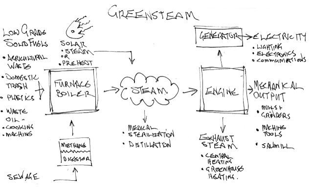
Greensteam leverages external combustion to simplify engine design and to enhance clean combustion of solid waste fuels. But external combustion is agnostic regarding heat source(s). An external combustion power generation system can draw upon hybrid heat sources, including solar, sewage methane digestion, geothermal or even nuclear. These can be mixed in varying proportions diurnally or seasonally, depending on context, and changing supply and demand. (For instance, solar panels could preheat boiler feedwater).
The furnace/boiler (for efficient production of steam) and the ‘engine’ (for conversion of steam to mechanical power) are two separate and separable projects. We will address both, with emphasis on engines in the early stages.
To leverage 100 years of materials, metallurgical and mechatronic advances since steam engine design development ceased.
-
A. To research and apply new plastics, composite materials, ceramics, and alloys (etc) to reduce wear, manage thermal expansion, thermal radiation, etc.
B. To find sweet spots between simplicity and efficiency, recognising that increase in efficiency are often coupled ort increases in complexity
C. To reduce moving parts and masses to a minimum, especially parts that wear or must be adjusted.
D. To seek application of mechatronics (sensor, microcontroller, powered output devices) to create autonomous self-regulation (homeostasis), to reduce mechanical parts count, increase energy efficiency and create real-time response. Note that, in a self-contained system, this implies generating the electrical power for the mechatronics from the engine itself and this generation is a cost.
E. To explore novel design solutions to problems such as valve control and drive trains.
F. Constraining design space - Engines are stationary and small scale - for domestic/small community electrical generation and mechanical tasks - pumping, grinding, driving machinery. Hence it has an optimal and fixed rpm range.
-
A. To leverage automated controls and the luxury of extended combustion time to build a furnace capable of cleanly burning a diverse range of combustible solid waste - including domestic waste, agricultural waste, industrial/medical waste and plastic waste.
B. To develop a mechatronic system of water temperature, oxygen, CO2, and steam temperature and pressure (etc) sensors and automatic valves and dampers (etc) to maximise efficient combustion and steam generation.
C. To use passive, low-tech and sustainable solutions wherever possible.
Project
Furnace
1. complete and clean combustion of dirty fuels
2. optimized harvesting of liberated heat as steam.
Prototype design is a vertical cylinder in form. Involves a pair of concentric vertical cylinders, the inner one being a fire-brick lined vertical combustion chamber with rising helical steam-coil. Fuel and air are fed in at the bottom where ignition occurs. At the top of the combustion chamber, combustion gasses are fed down a surrounding annular chamber, also insulated, containing a descending water preheat coil. This is topped by a spherical and insulated steam reservoir. Waste gasses exit to further heat scavengers, scrubbers, etc. Water is fed in via a (hopefully passive) feedwater system perhaps driven by exhaust gasses from furnace, or steam-condenser pump from engine. Condensate from engine exhaust is fed hack into feedwater system.
Project
Engines
The Greensteam first generation prototypes
In Spring2020 the project will develop models of simple engines in Solidworks, based on designs previously developed by professor Penny. This modelling will permit theoretical testing and design enhancement. This modelling and simulation will result in determination of several designs to be physically realized and will provide specifications and dimensions for physical production of 25- 50% scale working models, planned for summer 2020.
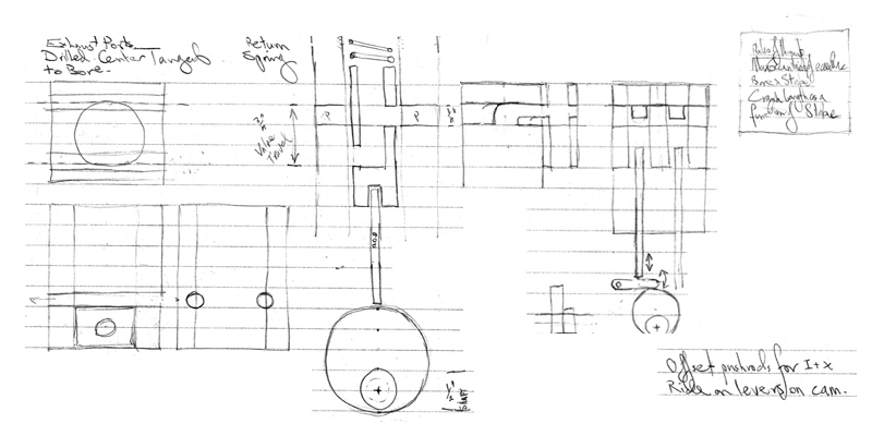
[drawing here]
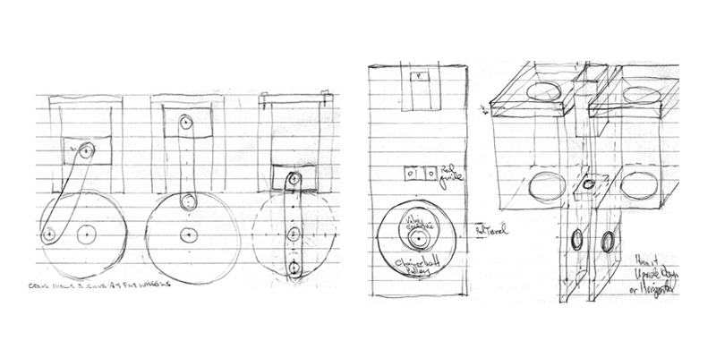
Three crankless single acting uniflow two-cylinder boxers with flywheel and pushrod actuated inlet valves (to be developed on the same plan/form factor, for comparison)
1. Scotch yoke, valve(s) actuated by pushrods driven by moving yoke.
2. Eccentric drive
3. Trilobe cam
4,5,6. Four-cylinder 90 deg opposed versions of 1,2,3, without flywheel.
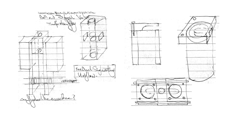
- Double acting uniflow cylinder with pushrod operated inlet spool valves.
- Simplex - single cylinder uniflow (Westbury Spartan type) wobble-plate or cam-driven piston valve
- Overhung crank DA V twin, cam-driven piston valves
- Triradial uniflow, eccentric/cam driven pushrod actuated piston valves
- Syzygy Engine - rotating tubular valve inline twin (center belt drive actuation of overhead transverse valve, or central rotating plug valve, bevel driven.)
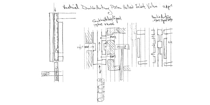
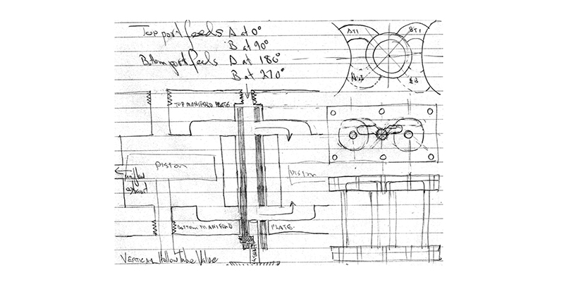
- Quadryzygy – Double acting two-cylinder overhung uniflow with bevel gear driven vertical hollow rotary inlet valve (or cam driven vertical reciprocating hollow spool valve).
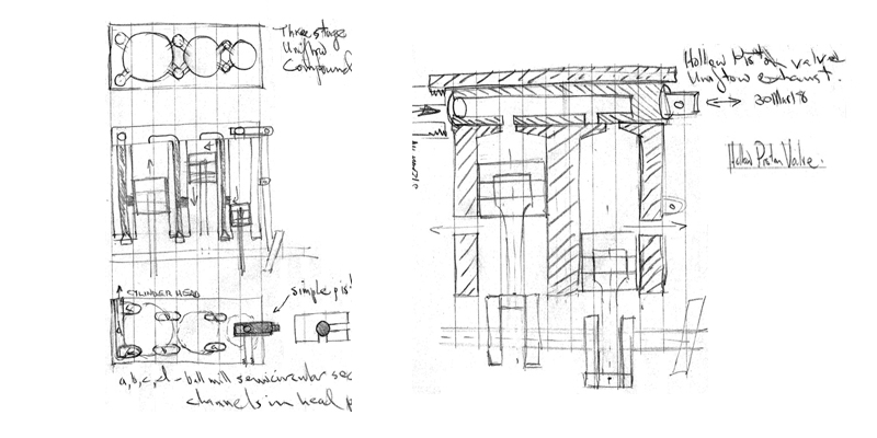
- Tryszgy - Inline three cylinder with dual transverse hollow rotary valves, end belt driven
- Blivet engine (fixed piston, moving cylinder body)
- Inline axial twin of the form illustrated here.
- Mechatronic/solenoid fast acting high pressure high temperature valve
Steam Engine
Design Theory
These notes and sketches are a result of technical design problem solving and explanation arising in Greensteam project research since early 2018. This is a multifaceted project is to consider the possible value of external combustion for stationary mechanical and electrical power generation, with a focus on small scale sustainable applications and on technological innovations that have occurred in the last 100 years - after the effective end of steam engine research. The design goals are always to find the sweet spots between efficiency, reliability and simplicity. This has led to a long-term interrogation of fundamental design issues, regarding engine and furnace/boiler design, and a feasibility studies into various novel design solutions, utilising modern metallurgy, composite materials, and mechatronics.
One potential advantage of external combustion engines (as opposed to internal combustion engines (IC)) is that the source of energized fluid and the production of mechanical power are entirely separable. A steam engine is agnostic about where it gets its power – solar panels, geothermal, biogas – steam is a universal fluid. This means we can address efficient steam generation entirely separately from mechanical conversion. It also means that questions of complete combustion of fuel is not subject to stringent time constraints for combustion (engine rpm). Having 100 or 1000 rimes longer to burn fuel is a significant advantage in realizing clean combustion and efficient extraction of energy.
On the engine side, we interrogated have every aspect of multifarious variants of steam engine design. We recognise that the conversion of reciprocating piston movement to rotating shaft is a fundamental mechanical inefficiency at the heart of all piston engines. For this reason, we continue to explore reciprocating-reciprocating conversion in our linear electrical generator research, and rotary-rotary in our tesla turbine research. We also recognize the efficiencies of a steam piston to piston pump topology for fluid pumping.
A major focus of Greensteam research is on (relatively) low-tech buildability and maintenance. There is clearly an advantage to minimizing the number of cylinders. This is the reason the traditional double-acting single cylinder engine with flywheel was the workhorse of the steam age. Apart from number of cylinders, multiple cylinder designs usually demand a crankshaft which is a highly sophisticated and difficult to make chunk of iron. We have concentrated on designs that avoid the use of crankshaft, including boxer designs, and overhung crank designs, while considering various methods of crankshaft fabrication.
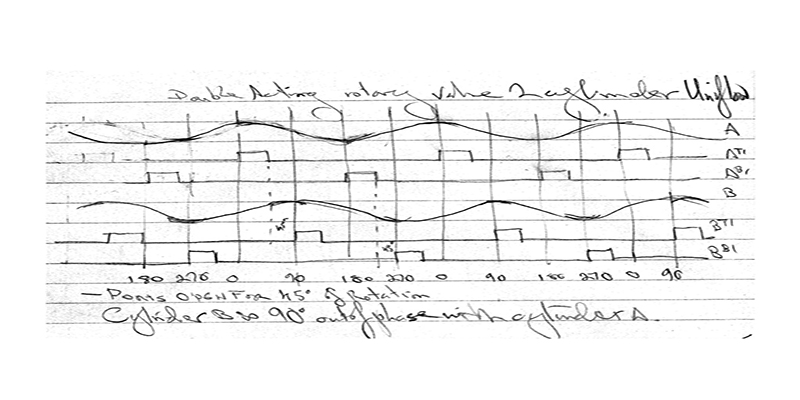
Valve design has been a preoccupation. While a neophyte to steam engine design assumes its all about pistons and cranks – because that is what is most obvious - the real action, the real complexity is in the valves, in timing, actuation, sealing, and ‘wire-drawing’. In most steam engine design, valve machinery comprises a substantial proportion of high precision moving parts. As a reciprocating part, valves and their actuators constantly consume energy in the constant acceleration and reversal of more or less massive moving parts. In addition, the commonly recommended poppet valve usually requires substantial return springs to ensure closure/return, and this energy is subtracted from the energy output of the engine. So any decrease in moving parts count or decrease in energy consumption of the valve train is truly advantageous. Hence our interest in novel solutions to the vale problem (such as the Penny-Rugh disc valve).
Given covid, our research process has had to adapt to a distributed mode with minimal physical development. The development process involves two rounds of intangible prototyping (sketches and CAD models, which will be followed by making small scale and full scale working physical prototypes. Most of the designs have originated in extensive ongoing historical research and longhand design development by Penny. Subsequently, students have CAD modelled (solidworks) and animated some of these designs. This virtual prototyping, involves extensive consultation with Penny and has revealed further details and design challenges.
Project history
This project was begun in early 2018 by PI Prof Simon Penny. It was supported with a CALIT2 UROP MDP (multidisciplinary design projects) grant 18/19 and was suspended summer19-winter20. It is located on UCI campus (Irvine California USA) and has been supported by the CALIT2 UROP MDP) initiative. Through this support undergraduate students are introduced to real world R+D. During covid, research has proceeded remotely.
Projects
Research & Design
Aspects of research program 2020/2021
- Historical/technical review of steam engine design.
- Development of several small-scale prototype engines based on Penny’s design/research (solidworks, etc) resulting in design refinement and dimensions and specifications for parts for several engine designs.
- Resolution of design issues - valve design, valve actuator design, drive train design, overall topology. Materials and components research.
- Fabrication training and tests.
- Prototype parts production using CNC router/mill and conventional mill/lathe machinery.
- Sensor/control research
- small scale high speed high pressure mechatronic steam valve development
- Design/build small scale generator/battery backup for onboard mechatronics
- Detailed modelling, specification and feasibility of Greensteam Furnace/boiler1. Including: fuel feed, combustion column, high pressure steam storage, safety valves, instrumentation and control components.
- Construction of prototype furnace/boiler.
Steam is dangerous. High pressure steam more so.
Explosions are to be avoided at all costs. Steam causes horrible burns to flesh.
All experimental procedures will be conducted with constant attention to safety issues.
Preliminary tests will always be made using compressed air and other ‘partially simulated’ methods.
Engine Design logic and research agendas
A steam engine converts energy liberated by expansion of supplied high-pressure steam to (conventionally) linear movement of a piston. The critical component of such a system is neither the piston nor the drive train but the valve mechanisms that regulate steam inlet and exhaust.
For historical reasons, mechanical power systems have gravitated towards rotational modes of power transfer. The reciprocating piston appears to be unavoidable, small scale turbines being impractical. Some applications exist for direct reciprocating output - steam hammers, reciprocating pumps, pile drivers etc. Reciprocating to rotational conversion (and vice versa) is inherently inefficient, but seemingly, a necessary evil. Simple and energy-efficient solutions are sought in all cases, including drive trains and valve control. Central to these are development of drive trains that do not require crankshafts (cam, eccentric and overhung) and alternatives to reciprocating valves and valve drive systems - belt and chain drives, eccentrics and swash plates, and rotating valves of various forms.
The rotary valve has been a holy grail of engine design for nearly two centuries. Rotary valves possess several significant advantages over reciprocating forms, including higher compression ratios and speeds, reduced complexity, meaning higher reliability and lower cost. Regrettably, competitive designs have been elusive, owing mainly to sealing and wear issues. Joseph Riedl developed a rotary valve for brass instruments in 1832. The famous Corliss steam valve was a hybrid reciprocating rotary kind. Some remarkable WWII aviation engines used them, as did some mid-century automotive and motorcycle experiments.
Though there is much to learn from internal combustion engine (ICE) design, it is important to denaturalize some design aspects. First, the ICE includes - obviously, internal combustion. External combustion eliminates some of the complexities of ICE. A major efficiency of the steam engine (compared to a 4 stroke ICE) is that every second stroke (or in the case of double acting cylinders - every stroke) is a power stroke. So, engines can be 25% of the size (cylinder volume) for the same power output. A conventional IC engine is dependent on a technically sophisticated crankshaft, and complex and energy consuming valve mechanisms.
In accordance with the principle of parsimonious engineering (Penny) - also known as the KISS principle (keep it simple, stupid), and with consideration of the IIABDFI protocol (if it aint broke, don’t fix it), several novel designs have been developed that minimise moving parts and sophisticated manufacturing processes. Greensteam designs seek alternatives to the crankshaft, and alternatives to the spring return poppet valve.
Furnace Design logic and research agendas
1. complete and clean combustion of dirty fuels
2. optimized harvesting of liberated heat as steam.
Given the goal of complete combustion of dirty fuels, a sophisticated monitoring and control system is assumed. How simple this can be is a subject for R+D. Maximising heat harvest implies: efficient heat transfer; minimization of heat exhaust; thermal insulation.
Prototype design is a vertical cylinder in form. Involves a pair of concentric vertical cylinders, the inner one being a fire-brick lined vertical combustion chamber with rising helical steam-coil. Fuel and air are fed in at the bottom where ignition occurs. At the top of the combustion chamber, combustion gasses are fed down a surrounding annular chamber, also insulated, containing a descending water preheat coil. This is topped by a spherical and insulated steam reservoir. Waste gasses exit to further heat scavengers, scrubbers, etc. Water is fed in via a (hopefully passive) feedwater system perhaps driven by exhaust gasses from furnace, or steam-condenser pump from engine. Condensate from engine exhaust is fed hack into feedwater system.
a. small fuel particle size. This may involve chippers or shredders that may be driven by power takeoff from engine.
b. optimizing temperature, oxygen and flow at various points in the column. This will involve instrumentation and active flow valves and dampers.
intuitive understanding of forces and mechanisms
Ability to pursue self-directed research, have a methodical research design development process, meet deadlines and communicate/collaborate with others.
Experience with materials, tool use and hands-on making practices (not just 3D printing).
The Greensteam first generation prototypes
Uniflow Boxer Engine
Tae Rugh
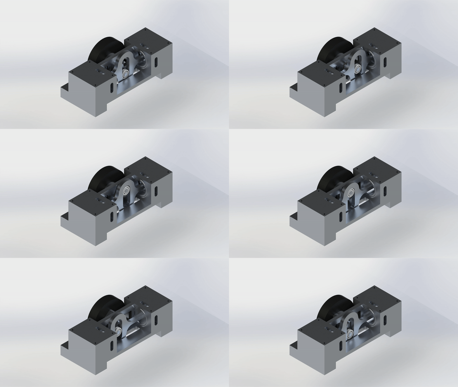
This engine has two diametrically opposed cylinders with corresponding pistons that are connected by a scotch yoke. Since this engine utilizes uniflow exhaust and the cylinders are opposite each other, one cylinder is always in a power stroke while the other is in its return stroke. A flywheel is necessary to ensure smooth running at top and bottom dead center. An overhung crank has been implemented in the design to drive the scotch yoke, since traditional crank shafts are very difficult to manufacture and require extreme precision. Inlet valve actuation is accomplished by 2 spool valves driven by a cam attached to the shaft.
Read the reportUniflow Triradial Engine
Tae Rugh

This engine has a triradial layout meaning the 3 cylinders are spaced equally 120° around the shaft. The advantage of this triradial cylinder layout is that the engine is able to run smoothly without requiring a flywheel. Each cylinder is offset slightly from the others so the piston rods may all attach to the same overhung crank. Behind the cylinder array is the first bearing plate, followed by the valve array, and finally the second bearing plate. 3 cam rods, one for each cylinder, track on a single cam and actuate poppet valves for inlet steam. Exhaust is accomplished through the uniflow ports at bottom dead center. The uniflow, poppet, and cam systems are reliable and effective, though there are some limitations to the control of valve timing.
Read the reportDouble-acting Uniflow Engine
Tae Rugh

This is a single-cylinder double-acting uniflow engine with bash valve actuation. The cylinder has steam inlets on both sides, so that while one side is in power stroke, the other is in return stroke. The bash mechanism means that this engine does not need to draw from the shaft’s rotation for valve timing, which significantly reduces the complexity and number of moving parts. The drawback is that control of inlet cutoff is severely limited by geometry such that the inlet must be open before top dead center for the same amount of time as it remains open after top dead center. A single uniflow exhaust port is located in the center of the cylinder block and used for both sides.
Read the reportDisk-actuated Triradial Engine
Tae Rugh

This engine has a triradial layout meaning the 3 cylinders are spaced equally 120° apart around the shaft. Each cylinder is offset slightly from the others so the piston rods may all attach to the same overhung crank. Behind the cylinders, the shaft drives 2 thin disks, on each side of the main plate, which act as the exhaust and inlet valves. Each disk has a slot--the shape of which determines timing and flow rate--which allows exhaust to escape to the atmosphere and inlet steam to enter the cylinders, both through milled manifolds in the main plate. The disks are forced to rotate with the shaft due to the key/keyway mechanism, but are not fixed for translational movement so that they may be pressure sealed against the plate.
Read the report3 Cylinder Inline Engine
Tae Rugh

This engine has 3 inline cylinders bored out of a single block. The 3 corresponding pistons are attached to the crankshaft with equal spacing of 120°. Due to this layout no flywheel is required. A drawback, however, is that a traditional crankshaft must be used, which is more difficult to manufacture than an overhung crank (which has been favored in many of our other designs). There are 2 rotating hollow pipes that run below the head of the cylinders, parallel to the crankshaft, and act as the inlet and exhaust valves. These pipes are linked to the crankshaft via a timing belt. The inlet tube is fed a constant supply of steam from one side and sealed on the other, while the exhaust tube is open on both sides to atmospheric pressure.
Read the report2 Cylinder Overhung Crank Engine
Tae Rugh

This engine has 2 cylinders, one on either side of a central flywheel. 2 overhung cranks drive the cylinders, diametrically opposed so that while one piston is in power stroke the other is in return stroke. This layout is akin to that of a bicycle, where the 2 pistons are the cyclist’s legs which force the pedals (overhung cranks) to rotate. Since there are 2 overhung cranks, no side of the shaft is free to act as the output driveshaft, so the flywheel also acts as a pulley which links with an external driveshaft. There are 2 rotating hollow pipes that run below the head of the cylinders, parallel to the crankshaft, and act as the inlet and exhaust valves. These pipes are linked to the crankshaft via a timing belt.
Read the reportTrilobe Engine
Michael Delessio
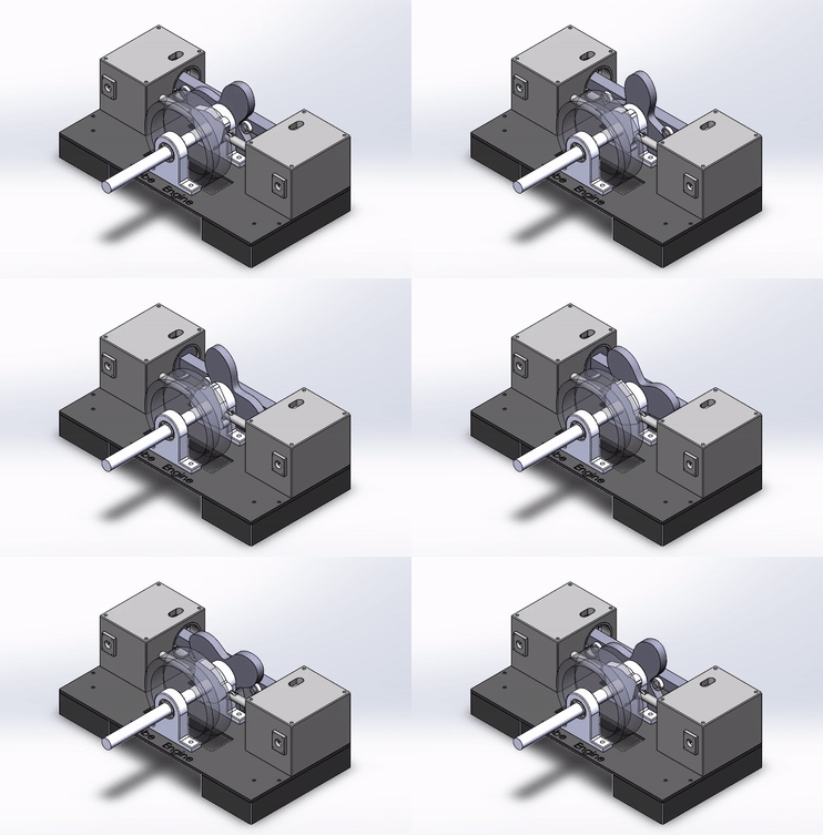
The Trilobe Engine designed for Project Greensteam is an external combustion steam engine that features an opposing two piston layout. The pistons are linked by a straight connecting rod and the translation of the pistons will be used to rotate a central “Trilobe” (or three lobed) cam. This Trilobe cam features peaks and troughs that correspond to Top Dead Center (TDC) and Bottom Dead Center (BDC) respectively.
Read the reportTrilobe Boxer Engine
Lee McEligot
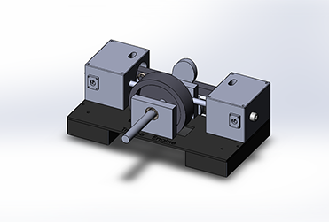
For the Fall 2020 Quarter, the design and development of the Trilobe Boxer engine was continued to its second phase and construction drawings were produced. Within the design and modeling process, redundancies were removed and certain parts were simplified that were previously overcomplicated. This includes the removal of the exhaust cylinder within the exhaust block assembly and simplifying the design of the shaft mount. Also within the modeling process, parts were refined, making them more accurate. A spring system was added to the exhaust block for the inlet valve system and added a bolt for easy access.
Read the report2 Cylinder Rotating Valve Engine 2.0
Shanwen Lo
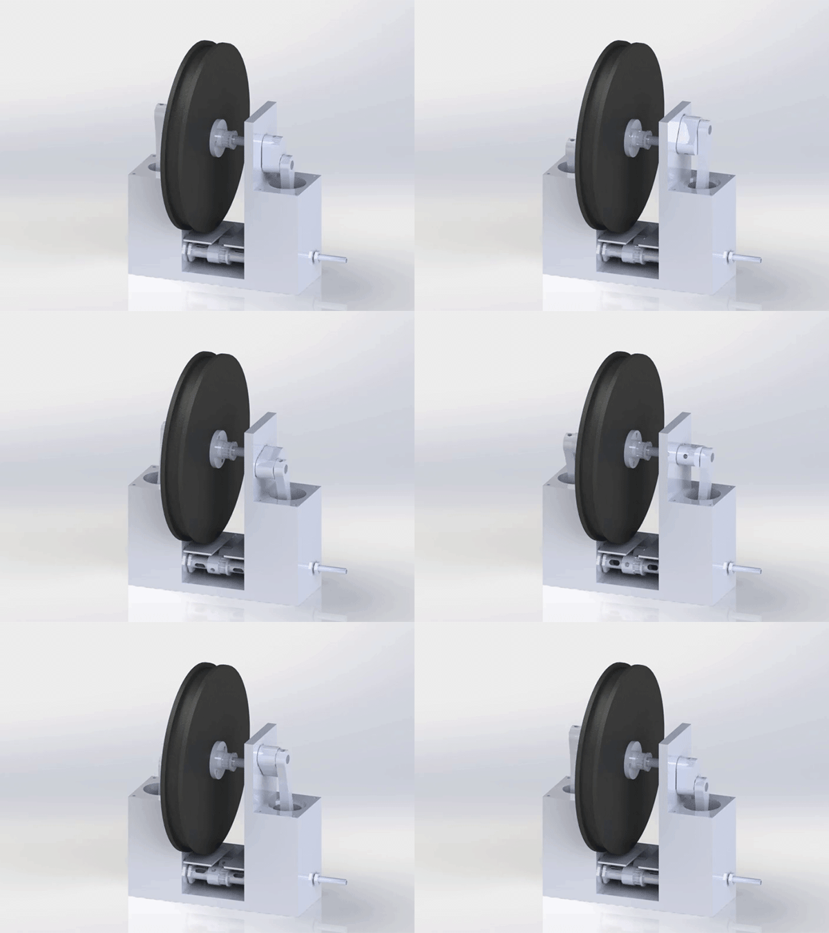
The rotating valve engine is very simple in how it operates due to the simple mechanism that manages the opening and closing of the steam values. The inlet and exhaust valves are a set of hollow cylindrical pipes that rotate in place and are linked to the crankshaft by a timing belt. This design eliminates the need for springs in order to close the valves - a factor contributing to the loss of efficiency in traditional valve mechanisms. However, this is also the main area of concern for the rotating valve engine where design solutions were needed.
Read the reportDouble-acting Compound Engine (Phase-I)
Tae Rugh
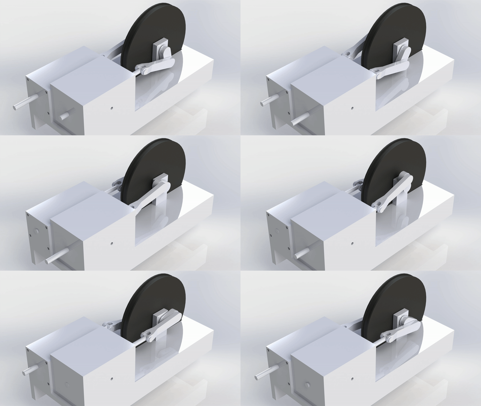
This is a 2 stage double-acting inline compound engine. This engine replaces the traditional cross-slide by extending the piston rod through the back end of the cylinder, thereby supporting the piston on either end. This increases the amount of required seals by two, but reduces moving mass and engine complexity. Steam enters the high pressure cylinder on both ends through bash valves. After high pressure expansion, steam exits through uniflow ports into a manifold which goes to the low pressure cylinder.
Read the reportScotch Boxer Engine
Eric Lopez
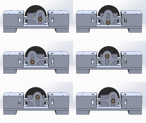
This engine utilizes the Scotch Yoke which translates linear motion from the cylinder into rotational motion while also reducing the complexity relative to that of a traditional crankshaft. Steam enters through the inlet valve on the sides of the cylinder blocks which cause the piston to expand. As the piston expands the rotation in the crankshaft also rotates the cam which causes the inlet valve to open and close allowing each piston to expand in an alternating fashion. When the piston is fully expanded steam is allowed to exit through the exhaust ports.
Read the reportTechnical Report
Valve Actuation Systems
Tae Rugh
Greensteam aims to design a modern steam engine that maximizes simplicity and frugality while maintaining high energy efficiency. The valve actuation mechanism presents one of the most important design challenges in achieving this objective. A number of potential options have been designed, each with its advantages and drawbacks.
Learn more
The Tesla Turbine Alternative
Tae Rugh
Nikola Tesla invented the bladeless turbine in 1913, but it has not achieved significant commercial use to this day. This is because--despite its highly efficient rotor flow which uniquely exploits shear-force--the Tesla turbine suffers from inefficiencies in the nozzle inlet. A recent experiment indicates that such inefficiencies can be drastically reduced by incorporating a plenum chamber directly before the inlet.
Learn more
Mechatronic Steam Valve
Samuel Hince Anthony Ochoa
Preliminary investigation was done into the feasibility of custom mechatronic, and mechanical, solutions. The research presented below has been conducted with an emphasis on small scale valves which might be appropriate for an engine of approximately 1 cubic inch per cylinder, operating at speeds at or below 500RPM. Additional assumptions include a supply pressure which can be varied to meet the valve’s capabilities and steam temperatures around 150-170 degrees celsius.
Learn more
Plastic and Waste Fuel Viability
Anthony Ochoa Jesus Lopez-Ochoa
This report covers the research/work done on the steam Boiler/Furnace section of the
GreenSteem project under Professor Simon Penny as of the end of Spring 2020. The focus of this quarter has been on the “burning (of) a diverse range of combustible solid waste - including domestic waste, agricultural waste, industrial/medical waste and plastic waste”, with an emphasis on the feasibility of cleanly disposing of various plastic wastes. Preliminary research was done into the plausible types of boiler design best suited for a low tech environment.
Learn more
Generator/Battery Charger
Adrien Sanding
The purpose of this project is to create an engine that converts landfill wastes into usable energy. For this quarter, emphasis was placed on ideal engine design, and conceptual plans for the furnace and mechatronic systems. My part in the project was designated into the mechatronic systems, more specifically, introducing a chargeable battery capable of keeping the system in motion, as the primary energy output of the system would be from the engine. Furthermore, sensors would be placed on the engine to be able to monitor the system's consistency and efficiency.
Learn more
Printrbot CNC
Michael Delessio
In this manual, we will discuss the Technical Specifications of the Printrbot CNC, Regular
Operation of the machine and compatible software, and various different Troubleshooting
methods that have been proven to solve issues relating to this particular machine and its
software.
Learn more
Steam Enginies
Critical Taxonomy
This synopsis is prepared as a primer for the Greensteam project. The Greensteam mechanical design research agenda is to explore unusual valve and drive-train types that offer reduction of parts count, especially moving parts count, and simplification of manufacture, while optimising efficiency, reliability and wear characteristics, at minimum cost. The Greensteam project will explore and exploit contemporary metallurgical, materials and mechatronics possibilities in pursuit of this agenda. The overall goal of the Greensteam project is rethink external combustion for sustainable, clean, small scale energy production in the C21st. Simon Penny, April 2020.
This review examines various designs and topologies of piston engines, primarily steam and internal combustion (IC) engines, but including compressors, pumps and other machines. The ‘age of steam’ - especially on west coast USA - is for most little more than a historical fantasy. We must remember that for 150 years, external combustion steam engines were the source of motive power for industry and transport, and were the context in which the discipline of engineering developed.
The distinction between external and internal combustion is fundamental here. External combustion was abandoned for historical reasons not directly related to engines themselves. It must be remembered that in 1920, there were more steam cars in the USA than internal combustion (diesel and gasoline combined). The viability of the combination of combustion and power-stroke in engine design is integrally connected with the discovery and exploitation of easily extracted oil, and the development of systems for handling a liquid fuel. This stimulated the growth of IC engines - it is just more convenient to squirt fuel than shovel it. That is why USA was largely home to the development of the automobile. If oil had been easy to find in UK (coal was just lying about), steam engines would have been oil-fired from the start, and we might still be driving steam cars.
Early engines (marine and stationary) operated at low pressures and single digit rpm and tended to be quite large. Many had cylinders so big you could walk inside them. The general trend in the evolution of piston engines has been toward higher pressure, higher rpm and smaller displacement. This could only occur in parallel with increasing precision in manufacture, better understanding of balance, lubrication and wear, and more sophisticated materials. For examples of all the aspects of the history of engines, the reader is directed to Douglas Self’s (wonderful) Museum of Retro-Technology
Ironically, the aspect of these designs that is simplest is the piston/cylinder system. Standard variants are single acting and double acting. In IC engines, single acting pistons include little end bearings or wrist pins. In older steam engines, this bearing took the form of cross slide.
In a standard IC cylinder, fuel/air is introduced between piston and cylinder head. In a conventional four stroke engine, this results in a power stoke every 4th stroke intake/compression/power/exhaust. In a two-stroke engine, power stroke happens every second stroke: power/exhaust. A single acting steam cylinder is two-stroke. Some steam cylinders are sealed at both ends (with piston rod emerging via a seal) and there are valves at both ends so one side of the piston is exhausting while the other is in power stroke. This means every stroke is a power stroke. The efficiencies are obvious.
Cylinder layouts
The simplest engine is single cylinder (single or double acting). Single cylinder engines require massive flywheels for momentum between power strokes.
- A layout of two linearly opposed cylinders is called a Boxer.
- A V-twin orientation has certain desirable torque characteristics. They sometimes actuate crankshaft via a knife and fork piston rod design.
- The triradial layout puts three cylinders at 120 degrees. These engines are self-starting, smooth operating and do not require flywheels. Pistons usually actuate an eccentric. In such engines, pistons usually are single acting and require little end bearings in piston.
- In inline multi-cylinder layouts - like most conventional IC engines - cylinder layout is determined by the geometry of the crankshaft. They also present a simple layout for valve control.
- Axial is a most unusual layout in which pistons move parallel to the crankshaft, driving it by swashplate or helicam style drivetrains.
In the conventional piston engine, reciprocating movement of pistons is concerted to rotary motion of a driveshaft. This is an inherently inefficient mechanical conversion and usually requires a substantial selection of precision engineered and dynamically balanced components. The crankshaft is the best understood piston engine drive train. Though common, their complexity should not be underestimated.
Overhung cranks.
The most obvious contemporary example of overhung cranks is the bicycle, where pedals are supported on one side only. This is clearly an unbalanced design, but has been traditionally deployed on steam engines, as well as other basic mechanisms – such as automobile wheels. In engines, permits dual cylinder operation without crankshaft, In the case of a double acting V twin, the equivalent of a 4 cylinder engine can be made without a crankshaft.
Scotch yokes
eccentric and cam drives. These types avoid the crank and or crankshaft, with substantial reduction in parts.
Ring gear drive.
This is an old and fascinating alternative to the overhung-crank. The ring gear or sun and planet gear was invented by the Scottish engineer William Murdoch, an employee of Boulton and Watt, but was patented by James Watt in October 1781 as an alternative to the crank, patented by James Pickard.
Wobble-plate/swashplate/Zcrank/helicam.
These are related solutions to driving the crankshaft in an axial topology. In the swashplate type, a disc is fixed obliquely to the crankshaft, and piston rods push against the plate sequentially, causing it, and hence the shaft, to rotate. This drive is found in some automotive AC compressors. In the Z crank design, an oblique plate attached to pistons rods is attached to a Z shaped crank that drives crankshaft. A related axial drive is found in the Michell engine 1920 and another in the Macomber rotary engine of 1912. Yet another variant has a sinusoidal campath on a axial cylinder. An early example is the Schott axial engine of 1870.
A more recent example of the helicam is the Dynacam/Revolvercam aviation engine. The axial rotary cam valve actuation is particularly parsimonious.
Sliding D valve.
This is the traditional steam engine valve, best suited to low pressure, low rpm high volume engines with double acting cylinders. The valve had the advantages of sealing by steam pressure and as they say, ‘wears in, doesn’t wear out’.
Corliss.
The Corliss valve was a reciprocating rotary valve system with complex control linkages and separate inlet and outlet ports located on opposite side of cylinder. This had the advantage that cooler exhaust gas did not cool the inlet passages.
Poppet.
The poppet valve, standard in IC engines are well adapted to high speed operation. As Tom Kimmel notably said, ‘there are poppet valves and valves that leak’. A major drawback is that heavy duty return springs are (usually) required to close valves opened by levers. A significant exception being the desmodromic valve system used in Ducati motorcycles, where the valve lever mechanism both opens and closes the valve.
Uniflow/Unaflow.
This is a principle that was adopted by two stroke IC engines in which an exhaust valve was replaced passive ports at BDC in the cylinder wall. Obvious advantage is a reduction of moving parts. Less obvious – cooler exhaust gas does not cool upper cylinder. Disadvantage is that some exhaust gas is recompressed on return stroke.
Reciprocating plug/piston/spool valves.
This is an entire class of cylindrical valves, usually pushed by pushrod. Usually separate intake and exhaust, though some combine both functions.
Rotating valves – disc, plug/vane, tubular, tubular plug vane hybrid.
Rotating or rotary valves have been an attractive but elusive goal for engine designers for 200 years. The obvious advantages being smooth continuous operation, more efficient than reciprocation. But sealing and lubrication problems have never been solved.
Almost always, valves are actuated from the crankshaft, which provides both timing and motive power. Main types include:
- Eccentric/cam actuated pushrod
- Chain/belt
- Bevel gear
- Wobble plate actuated rocking shaft
Timing refers to when valves open and close (and therefore how long they are open for) with respect to the position of the piston in its stroke. Mechanical valve mechanisms are normally driven off the crankshaft. Combined inlet/exhaust valve mechanisms have the (potential) drawback that timing cannot be separately adjusted.
In an IC engine, combustion time is fixed, so the higher the rpm, the sooner fuel must be ignited in order to extract all expansion energy from the explosion before BDC. In a steam engine, drive is produces in two ways, first the introduction of high-pressure steam into the cylinder, then expansion of same steam. These are two separate processes. In both cases, for efficient functioning, valve timing must be advanced as rpm rise. Flexible, quickly responsive and independent control of valve ‘advance’ and open times is central to an efficient engine.
Wobbler engine (oscillating cylinder).
Compound engine
A class of efficient, usually large, stationary and marine engines was developed in the latter C19th. They were called ‘compound’ because the steam passed sequentially from a high pressure cylinder to a larger low pressure cylinder, and often to a third stage, each stage harvesting more power from the single charge of steam.
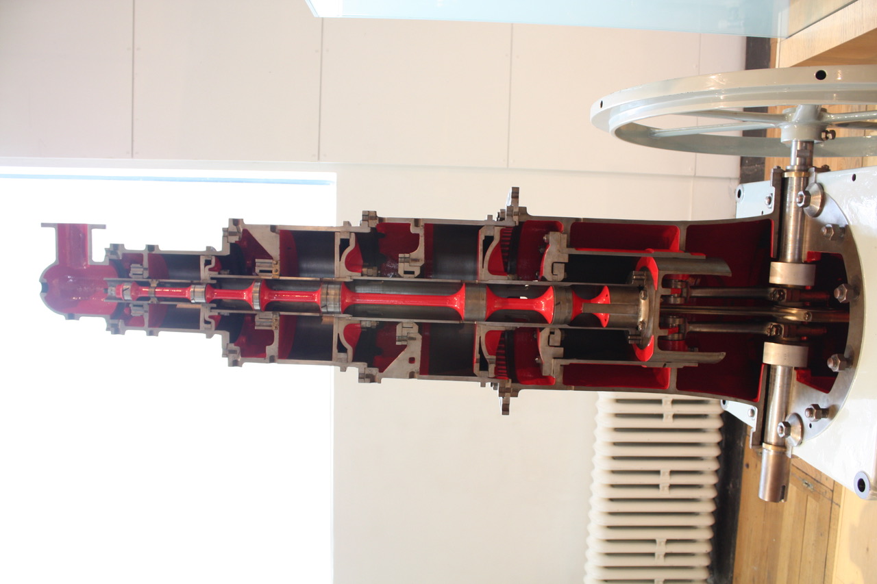
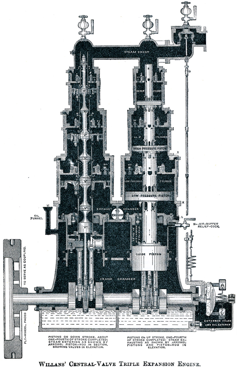
One of the most unusual architectures was known as a steeple compound engine, on account of its appearance. In such designs, all cylinders drove a single, axial piston rod, so thrust must have been extremely asymetrical, hence the large flywheel. Depicted is a particularly interesting Willans design, in which the valves operated inside a hollow piston rod. Valve shaft was driven by an eccentric located between two ‘big-end’ bearings on the crankshaft. The pistons were thus annular in shape.
Axial multi-piston engines
Arragements with multiple cylinders axially inline have been used, sometimes with no rotary output, often for pumps: a double acting steam cyllinder driving a double acting pump cylinder. This avoids energy losses due to linear to rotary movement. See this example: Dual piston cylinders for instance.
Dan Gelbart's unique uniflow with solenoid retained bash valve and in-piston relief valve.
